Apollo Launch Facilities
In order to launch the unprecedented massive Apollo Saturn rocket, the construction of many special dedicated facilities was required, including the iconic VAB.Vehicle Assembly Building(VAB)

This is a building for assembling launch vehicles, located about 3 miles (approximately 4.8 km) from Pad, also called Vertical Assembly Building.

The building protects vehicles and engineers from wind and rain during long-term assembly and checkout operations. It was built between November 1962 and June 1965. Developed by Architectural Engineering Consortium URSAM(Urbahn, Roberts, Seelye, and Moran). Its volume is 13 million cubic feet, length is 716 ft (about 218 m), width is 518 ft (about 157 m), and it occupies an area of 8 acres. And the weight of the used steel frame reaches about 60,000 tons. Height is comparable to a 40 or 50-story skyscraper, and area is comparable to the Yankee Stadium. It is one of the largest buildings on earth.
The building is designed to stay within 6 inches (15 cm) of shaking when receiving 62 mph (100 km / h) of wind. The building is covered with an outer wall of over 100,000 square meters of insulated aluminum panels fixed to steel girder to protect the building from shock waves from the launch pad. And for windows occupying a total area of 6,440 square meters, 1.2m x 3.7m impact resistant translucent plastic panels are used.

Four large inverted T-shaped doors are 456 ft (about 139 m) high,
and lower opening is 149 ft (about 45 m) width and 113 ft (about 34 m) high.
And upper area width of the door is 76 ft (about 23 m).
This is the size that the Statue of Liberty standing in New York can pass through easily.

Interior of the VAB is divided into tall High-bay for assembling and checking out the vehicle vertically,
and short Low-bay for testing each stage delivered by the manufacturer individually.
And Transfer Aisle for moving parts from Low-bay to High-bay penetrates the center from north to south.

Large Gravity Ventilators are installed on the ceiling of High-bay, which allows the entire High-bay air to be replaced in one hour. Low-bay is equipped with a 9000 ton capacity air conditioning system sufficient to cool 3,000 homes, keeping the temperature comfortable around offices, labs, work rooms, spacecraft, and ML pedestals.
| Length | Width | Height | |
|---|---|---|---|
| High-bay | 442 ft (approx. 134.7m) | 518 ft (approx. 158m) | 525 ft (approx. 160m) |
| Low-bay | 274 ft (approx. 83.5m) | 442 ft (approx. 134.7m) | 210 ft (approx. 64m) |


High-bay is internally divided into four rooms, and at the same time four Saturn Vs could be assembled and maintained. And in the future, it was designed to be able to add two more rooms. However, no expansion was actually done, and the fourth High-bay was used as a warehouse. Collapsible five work platforms are attached to the High-bay wall and are intimately attached around the vehicle to provide a footing for work. There are positioned with a 20 ton hydraulic jack and can be deployed and stored within 10 minutes.
Low-bay has eight Stage preparation and Checkout cells. Here is a system that simulates the interface of each stage.
In the VAB, as many as 141 lifting devices are installed, from mechanical hoist with load capacity of 1 ton, to two bridge cranes with load capacity of 250 ton. The 250 ton bridge crane shares one in two bays, with a lifting height of 456 ft (about 139 m) and a travel distance of 431 ft (about 131 m).
In 1976, Stars and stripes was drawn on the south wall of High-bay, which size is 64 m x 33.5 m (209 ft x 110 ft). The stripe is 9 ft (about 2.7 m) wide : wider than a tourist bus. The width of one star is 6 ft (about 1.8 m), which is as large as a car.
Launch Control Center(LCC)

This is the building that controls the final countdown and launch. Control here from vehicle assembly and testing, to take-off and pass through the launch tower ('Clear the Tower'), the Mission Operations Control Room (MOCR) in Houston takes over after that. The building is four stories high, southeast of the VAB and connected by a long walkway with the VAB High-bay. The size is 380 ft (about 115.8 m) x 180 ft (about 54.9 m), and the development is URSAM like VAB.

Initially there was a proposal to install LCC on the roof of VAB's High-bay, but this was canceled mainly in terms of cost.

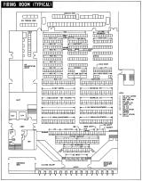
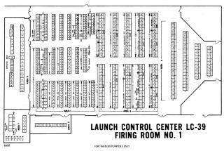
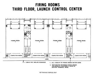
On the first floor of the building there are service and support area, management center, dining, office etc, and on the second floor there are telemetry reception and tracking equipment. On the third floor there are 4 firing rooms (launch control rooms) and computer rooms, each connected to 4 High-bays. And these can individually check out and test each vehicles. Each of firing room is 28m wide and 46m deep, with no pillars. There are visitor's area (bubble-room) in the mezzanine floor on the window side. On the fourth floor, large LIEF (Launch Information Exchange Facility) display screens are installed for each firing room, and various informations are displayed to the staff of firing rooms.

The Pad side (northeast side) of firing rooms are equipped 2 cm thick glass with adjustable sun visor, embedded in special aluminum frames, and show directly rocket rising from launch pad. The window is 24m wide and 7m high, and filters that remove heat and glare cut 72% of the outside light. And infrared lights for taking condensation are provided on the outside of this window.

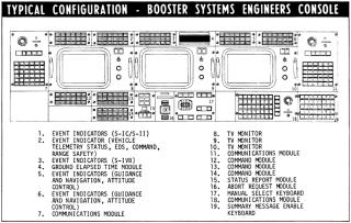
Nearly 450 consoles are set up in each firing room, operated by members of Saturn Booster stage development companies, Radio Corporation of America, General Electric, Saunders, Symetrics, International Telephone and Telegraph, NASA, Eastern Test Range. These consoles were arranged to allow Boeing, North American and other engineering teams to sit together at each company. The design responsibility for each console was at the company that used it, but the design was coordinated by the Launch Operations Center (LOC).

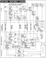
Two sets of computers were used for checkout and countdown. ACE (Acceptance Checkout Equipment) was used for the Apollo spacecraft, and the Saturn ground computer system was used to check out each stage of the vehicle. The Saturn ground computer system is comprised of RCA 110A computers installed in each of LCC and ML, and DDP 224 display computer installed in LCC. One DDP 224 could control more than 20 CRT displays. The RCA 110A sent 2,016 signals to vehicle and received 1,512 signals. 112 of communication channels have been set up to make voice calls between astronauts, launch teams, and flight directors. The Propellant tanking computer system (PTCS) installed at LC-39 was used to control the supply of fuel and oxidant, and the replenishment of evaporation.
Drawings
Crawlerway

This is the trail of the Crawler Transporter(CT) , which connects Pad A and Pad B from the VAB. To move over 7,700 tons (58 tons per square meter) of Crawlers, Mobile Launcher , and rocket in total over the wetlands of Merritt Island, special roads had to be developed.
It consists of two pavements, TRACKWAY A and TRACKWAY B, according to the width of the Crawler track. It was built from November 1963 to August 1965. Each of the two pavements has a width of 40 ft (about 12 m), and the entire width of one lane is 131 ft (about 40 m). This width is comparable to an 8-lane highway. And the sea level is 2.3m.

Sand is compressed by vibroflotation to a depth of 7.7 meters below the pavement. On top of that, a 1.4 m thick pavement was constructed using crushed stone. Pavement uses Alabama River gravel to achieve a very specific low friction surface, with a coefficient of friction of 0.3 or less.
Mobile Service Structure(MSS)

This is a maintenance tower for maintaining the vehicle installed in the Pad. Like ML, it is transported to Pad by Crawler Transporter. And it wraps the top of the rocket completely 360 degrees and provides a clean room for maintenance of Command Module(CM), Service Module(SM), Lunar Module(LM). Then removed from the pad at T-7 hours before launch.

It was built in 1965. The height is 410 ft (about 125 m) from ground. The height from the Mobile Launcher(ML) deck (Level 0) is 363 ft (about 110.6 m). The size is 135 ft (about 41 m) x 132 ft (about 40 m), and the weight is 10.5 million pounds (about 4,760 tons) the same as ML.
Five work platforms are attached to the top.
The lower two can move up and down with power. The remaining three can be repositioned but not powered.
The base section includes mechanical equipment room, operations support room, communication and television equipment room, and other equipment compartments.


When not in use, parked on the Park Site at the junction of Pad A and Pad B along the crawler way.
It was originally planned as "arming" tower for attaching retro rockets, ullage rockets, explosives for stage separation, etc. to the Saturn rocket installed on the launch pad, but the weight exceeded the crawler's allowable loading weight. Because of this, rockets and separation charges were attached at the VAB, and detonators were attached from service arm just before launch.
Launch Complex LC-39A and LC-39B

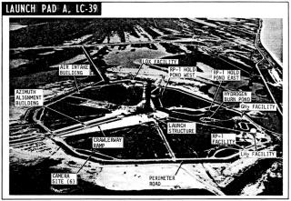
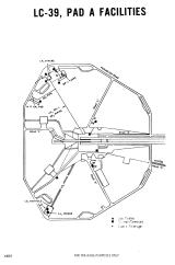
The Pad and related facilities such as VAB, LCC, ML, MSS, Crawler, Crawlerway and the fuel storage e.t.c. in the vicinity are collectively called Launch Complex. In particular, the launch pad itself is called a 'Pad'. LC-39A (Pad A) and LC-39B (Pad B) were built for the Saturn V. It was built from November 1963 to October 1965. When viewed from the sky, it has an almost octagonal shape, and its end-to-end width is about 3,000 ft (about 910 m). The area is about 130 hectares and the top of the launch pad is 48 ft (about 14.6 m) above sea level. For safety reasons, each pad is 8,730 feet (about 2,661 m) away from each other.

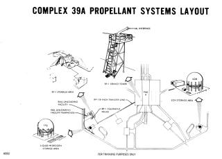
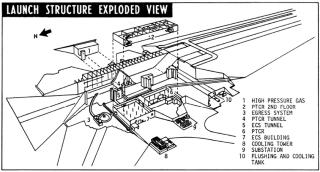
LOX (900,000 gallons), RP-1 (86,000 gallons) and LH2 used as rocket fuel, are stored in tanks installed around the launch site. Helium and nitrogen gas are stored at 6,000 to 10,000 psi in a tank of high-pressure-gas storage facility located underground on the east side of the Pad.
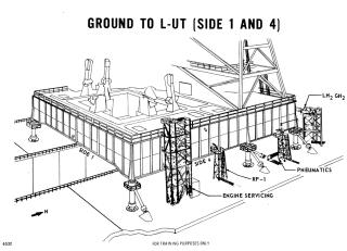
In the center of Launch site, there is a Hardstand made of concrete and iron, on which ML and MSS are fixed.


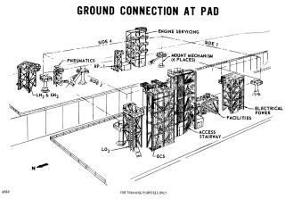
On the west side of the Pad are the two-story Pad Terminal Connection Room(PTCR) and the one-story Environmental Control Systems room(ECS). PTCR stored electronic devices that connect communication and digital data link transmission lines from the control center to the mobile launcher. ECS contained air conditioning system and water supply system. In the basement to the north of the ECS, there is a circular heat-resistant room (Blast room), which is one of the Emergency Egress System, where engineers can escape in an emergency such as a fire.
Exhaust flame trench

Exhaust flame trench measures 59 ft (about 18 m) wide and 500 ft (137 m) long, and extends north-south from the center of the pad. This trench could not be made below ground level because the groundwater surface around KSC is very close to the ground surface. For this reason, Hardstand was also built at a height of 42 ft (about 13 m).
The surface had to withstand a temperature of 1,922 Kelvin (3,000 degrees Fahrenheit) and a flame speed of four times the speed of sound. For this purpose special refractory bricks were fixed to the wall by interlocks, mechanical anchors and modified epoxy cement. The adhesive side of the concrete to attach the bricks required a smoothness of 3 mm per 3 meters. As a result, the temperature of the concrete portion at launch was kept at 98.6 degrees Fahrenheit or less.
This trench was designed to the width of the crawler transporter tread. And based on this Exhaust flame trench and Flame Deflector designs, the width and height of the pad were determined.
Flame Deflector

This is a deflector for flowing vertical S-IC exhaust into a horizontal Exhaust flame trench. The launch pad was made as low as possible to keep the rocket out of the wind. For this reason, it was necessary to devise a flow of rocket exhaust horizontally. This is the Exhaust flame trench and Flame Deflector.

This Flame Deflector has an inverted V-shape, and its skeleton is made of iron. The tip is replaceable and coated with ceramic (concrete consisting of a volcanic ash aggregate and a calcium aluminate binder). It is 13 meters high, 15 meters wide, 29 meters long and weighs 317 tons. Two units are installed for each launch pad, and one of them is moved directly under the launch pad by the rail system before launch. At launch, the exhausts of S-IC's outside four engines hit inverted V-shaped part, and running water is injected here to suppress shock waves. Center engine exhaust strikes the ceramic tip and is slowly eroded by the heat. The intense heat energy then becomes high heat particles and is released to the atmosphere through the flame trench along with the exhaust.
Other Facilities

The Theodolite Building is approximately 100 ft (about 30.5 m) away from the center of Pad A towards the VAB. At the junction of Pad A and Pad B at Crawler Way, about 7,000 ft (approximately 2134 m) from Pad, there is a Park Site where MSS and Crawler Transporter are parked. At the midpoint between the VAB and the Park Site, there is a HP Gas Facility / converter-compressor facility with a spherical tank. Liquid nitrogen and helium were supplied from here to the tanks of the high-pressure-gas storage facility below each pad. A railway line was also laid here to transport the gas. In addition, near the VAB is the HP Gas Storage Building. To the north of the VAB is the Mobile Launcher Refurbish Area, where three MLs can be parked and maintained.

Launch
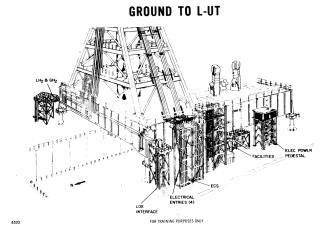
When ML arrives at Pad, vehicle was installed in a direction such that LUT is on the north side, position I of S-IC is on the east side, and fin A of S-IC is 45 degrees north of the position I. LUT hammerhead crane is fixed in a direction rotated 90 degrees clockwise (west direction). LUT is installed on the base of Pad, and service lines (fuel, electricity, etc.) in the Pad were connected to the LUT.
Final checkout begins when MSS leaves the tower 7 hours before launch. During fueling, CM hatch was closed and access arm was folded and secured to the tower. When fueling is complete, access arm was deployed, checkout crew leaves the Pad, and astronauts board. The access arm is folded at T-60 sec.
Drawings
Related books and videos
-
Apollo Mission Control: The Making of a National Historic Landmark

Springer 2018-07-04 USD39.99
This book describes the history of this now iconic room which represents America�s space program during the Gemini, Apollo, Skylab, Apollo-Soyuz and early Space Shuttle eras. It is now a National Historic Landmark and is being restored to a level which represents the day the flight control teams walked out after the last lunar landing missions.
-
Mission Control

Gravitas Ventures 2017/07/27 USD24.99
At the heart of the Apollo space program and a remarkable decade of achievement was the team who worked in Mission Control.They were born against a backdrop of economic turmoil and global conflict. Some came from a rural lifestyle little changed from the 19th century. Others grew up in a gritty, blue-collar America of mines and smoke stacks. They ranged from kids straight out of college to those toughened by military service. But from such ordinary beginnings, an extraordinary team was born. They were setting out on what JFK called: “The most hazardous, dangerous, and greatest adventure upon which mankind has ever embarked” and through their testimony ? and the supporting voices of Apollo astronauts and modern NASA flight directors ? the film takes us from the faltering start of the program through the Mercury and Gemini missions, the tragedy of the Apollo 1 fire to the glories of the Moon landings.


