


 Create a new MODEL / setting on radio

The same operation is possible with any radio that uses OpenTX / EdgeTX. However, keyswitch assignments / functions differ depending on model, and screen / menu configuration differs depending on installed version of OpenTX / EdgeTX.
このページを日本語で見る
Table of contents
-
RadioMaster Zorro 2.4GHz 16CH Hall Sensor Gimbals

RadioMaster 2022/02 USD89.99
On-board firmware:EdgeTX(OpenTX)
Featuring an ergonomic design, large bright LCD screen in the perfect viewing position, travel adjustable HALL sensor gimbals, a nano size external RF module bay

 (US)
(UK)
How to use RadioMaster Zorro
(US)
(UK)
How to use RadioMaster Zorro
Register a new MODEL input area
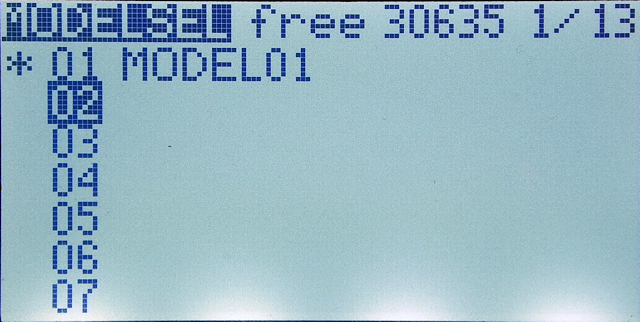 Before registering aircraft information in radio, register a new area to enter the "MODEL".
Open "MODELSEL screen" from the main screen and register a new area.
Before registering aircraft information in radio, register a new area to enter the "MODEL".
Open "MODELSEL screen" from the main screen and register a new area.
See below for how to operate MODELSEL screen.
On radio: SETUP screen settings
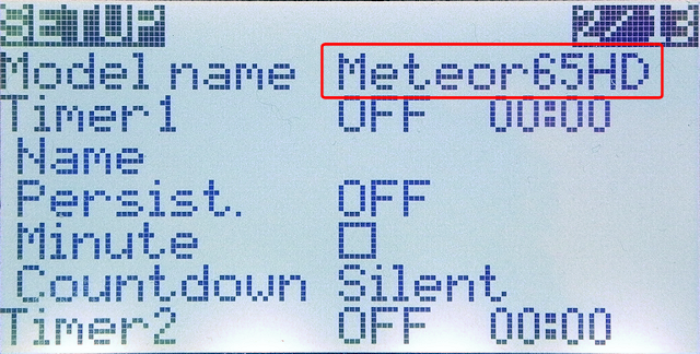 After registering the area for entering "MODEL" and selecting the MODEL, open "SETUP" screen.
This is the screen for basic model settings.
After registering the area for entering "MODEL" and selecting the MODEL, open "SETUP" screen.
This is the screen for basic model settings.
Let's name this model first. Move cursor to "Model name" field and press [ENTER] key to enter edit mode.
For information on how to enter strings, see Basics of OpenTX/EdgeTX radio operation .
Basics of OpenTX/EdgeTX radio operation
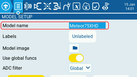 Color display/touch panel models can be set in the same way, just with a different screen design.
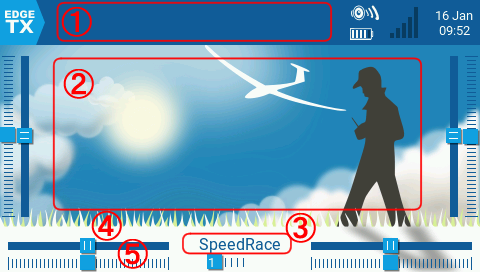 Depending on the type of radio, you can change the design of the Main screen or set the Model Image.
Model Image is displayed as an image of the selected aircraft on main screen and
MODELSEL screen
.
See below for details.
Depending on the type of radio, you can change the design of the Main screen or set the Model Image.
Model Image is displayed as an image of the selected aircraft on main screen and
MODELSEL screen
.
See below for details.
However, these settings are not required, especially for controlling FPV drones. You can omit these.
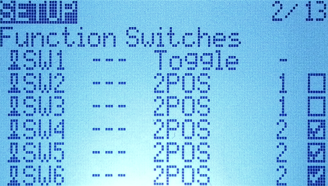 On the front panel of recent radios that support OpenTX / EdgeTX, there are products with 6 buttons.
These switches are called "function switches".
Different behavior can be set for each "MODEL" set in the radio.
See below for details.
On the front panel of recent radios that support OpenTX / EdgeTX, there are products with 6 buttons.
These switches are called "function switches".
Different behavior can be set for each "MODEL" set in the radio.
See below for details.
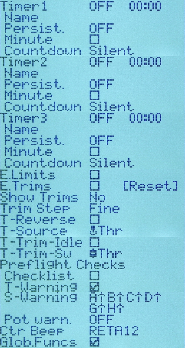 There are many settings under "Model name", but this time I will skip from "Timer" to "GlobFuncs" with the default values.
For reference, click image to see these default values.
There are many settings under "Model name", but this time I will skip from "Timer" to "GlobFuncs" with the default values.
For reference, click image to see these default values.
See How to use timer for how to set the timer.
For details on these all setting items, see MODEL SETUP setting items explanation .
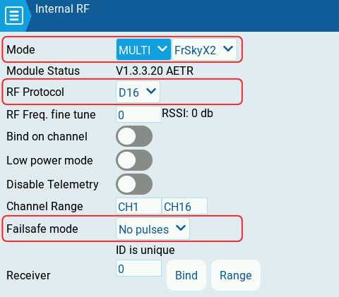
 The important thing on SETUP screen is transmitter settings.
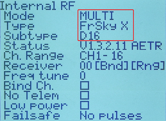
When using a transmitter built into the radio, set "Internal RF (built-in transmitter)" field,
When using a transmitter installed in module bay, set it in "External RF" field.
Here, set communication protocol of drone that you checked in advance.
The important thing on SETUP screen is transmitter settings.
When using a transmitter built into the radio, set "Internal RF (built-in transmitter)" field,
When using a transmitter installed in module bay, set it in "External RF" field.
Here, set communication protocol of drone that you checked in advance.
Drone to be bound this time uses "D16" type in the Frsky protocol. Select "MULTI (Multi-Protocol Module)" in "Mode" field. Select "FrSky (FrSky X)" for "Type" and "D16" for "Subtype". No other changes are required.
This setting screen changes depending on the protocol selected. Depending on the protocol, it may be necessary to set other items as well. Check website or instruction manual of FC board or RX board.
For information on how to set the communication protocol when using the ExpressLRS (ELRS) protocol, see How to set up ExpressLRS transmitter .
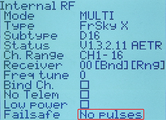 Depending on communication protocol selected, "Failsafe / Failsafe mode" field on this screen allows you to specify how the drone behaves when communication between radio and drone is lost.
See
Failsafe settings
for details.
Depending on communication protocol selected, "Failsafe / Failsafe mode" field on this screen allows you to specify how the drone behaves when communication between radio and drone is lost.
See
Failsafe settings
for details.
Failsafe settings
 Color display/touch panel models can be set in the same way, just with a different screen design.
On radio: INPUTS screen settings
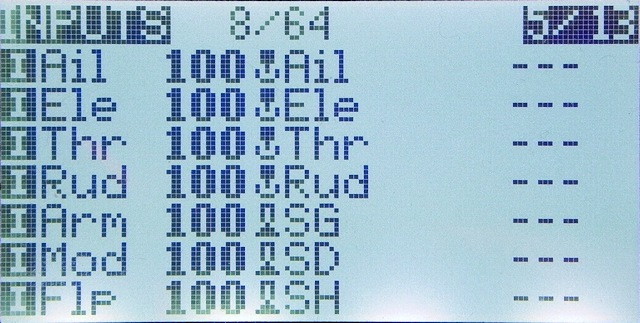
After setting SETUP screen, let's set INPUTS screen next. Press [PAGE] key, etc, several times to open "INPUTS" screen.HELI SETUP screen and FLIGHT MODES screen will be skipped.
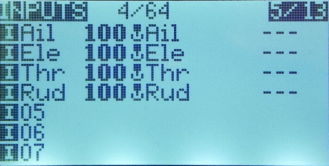 This screen lists input devices used for maneuvering. It can also be thought of as a screen that assigns input devices such as sticks, switches, and LOGICAL SWITCHES mounted on the radio to virtual channels defined inside OpenTX/EdgeTX.
Number / name of the virtual channel is lined up after
This screen lists input devices used for maneuvering. It can also be thought of as a screen that assigns input devices such as sticks, switches, and LOGICAL SWITCHES mounted on the radio to virtual channels defined inside OpenTX/EdgeTX.
Number / name of the virtual channel is lined up after
First four channels are already assigned Aileron, Elevator, Throttle, Rudder in that order. This allocation order is determined by specifying "RX channel ord (Default channel order)" field near the end of RADIO SETUP screen in RADIO menu. Since it is a virtual channel, it can be assigned in any order. If this order does not match the aircraft you are binding to, change it on next MIXES screen.
See OpenTX/EdgeTX radio initial setup procedure for how to operate the RADIO menu.
OpenTX/EdgeTX radio initial setup procedure
 Assign switches to virtual channels 5-8.
On the screen above, move cursor to "
Assign switches to virtual channels 5-8.
On the screen above, move cursor to "
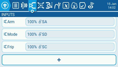
For color display/touch panel models, select "+" at the bottom of the list and press [ENTER] key.
 Then the screen will look like this.
There are many settings that can be made regarding the behavior of input device, but this time we will only assign the switch.
Then the screen will look like this.
There are many settings that can be made regarding the behavior of input device, but this time we will only assign the switch.
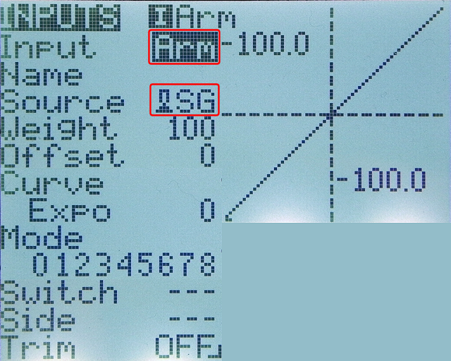
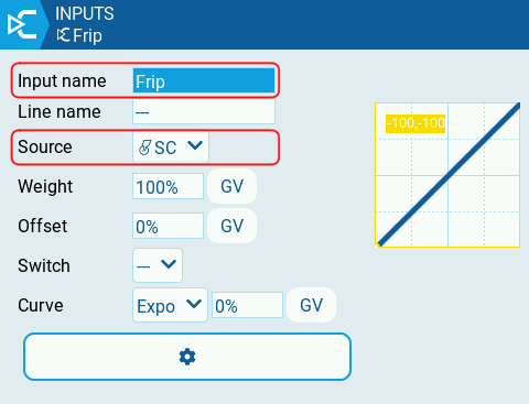
In the "Source" field, select SG (Switch G) that will be the input device. You can also name this virtual channel in "Input" field in three letters. Since Arm is assigned to SG this time, I named it "Arm". You can leave the name blank.
Similarly, I assigned SD and SH to virtual channels 6 and 7 and named them "Mod" and "Flp". Since it is a virtual channel, it can be assigned in any order.
For details on these all setting items, see MODEL INPUTS setting items explanation .
 Color display/touch panel models can be set in the same way, just with a different screen design.
In "Source" field, you can also specify the input device by operating actual switch. If you press [ENTER] key in "Source" field to enter edit mode and then move SA switch, for example, "SA" will be set in "Source" field.
If you simply assign one switch to one channel, you can register it directly in "Source" field of next MIXES screen without registering the switch on this INPUTS screen. If you register on the INPUTS screen, you can make more complicated specifications such as assigning multiple switches and dials to one channel with a specific mixing ratio.
 When screen looks like this, setting of INPUTS screen is complete.
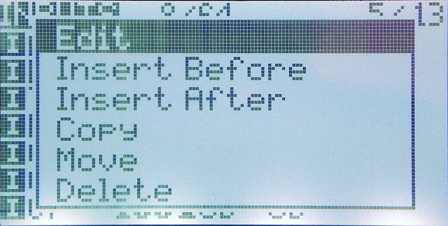 If you place cursor on a channel that has already been entered, and press and hold [ENTER] key, a screen like this will be displayed.
You can edit, insert new INPUTs before and after, copy, move, and delete.
If you place cursor on a channel that has already been entered, and press and hold [ENTER] key, a screen like this will be displayed.
You can edit, insert new INPUTs before and after, copy, move, and delete.
You can also click [ENTER] key on a channel that has already been entered to select, and then UP / DOWN cursor keys, etc, to change the display order.
On radio: MIXES screen settings
Next, let's set MIXES screen. Press [PAGE] key, etc, several times to open "MIXES" screen.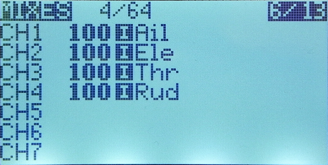 This screen defines which input device (virtual channel) defined on INPUTS screen is transmitted to which physical channel of receiver (aircraft).
Destination channel number is lined up on the far left, and the number of assigned virtual channel is lined up next to it.
This screen defines which input device (virtual channel) defined on INPUTS screen is transmitted to which physical channel of receiver (aircraft).
Destination channel number is lined up on the far left, and the number of assigned virtual channel is lined up next to it.
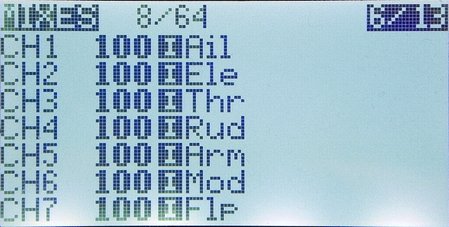
First four channels are already assigned Aileron, Elevator, Throttle, Rudder in that order.
 When channel maps do not match
If CH1 to CH4 stick allocation order is different from channel allocation order on aircraft, open that channel and select the correct stick name in "Source" field.
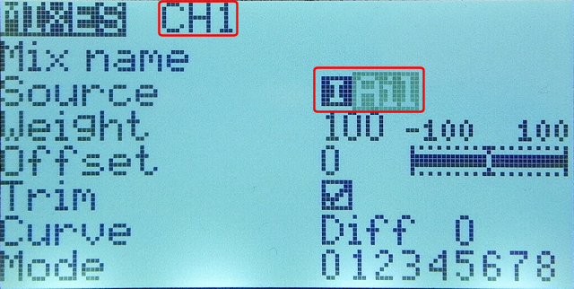
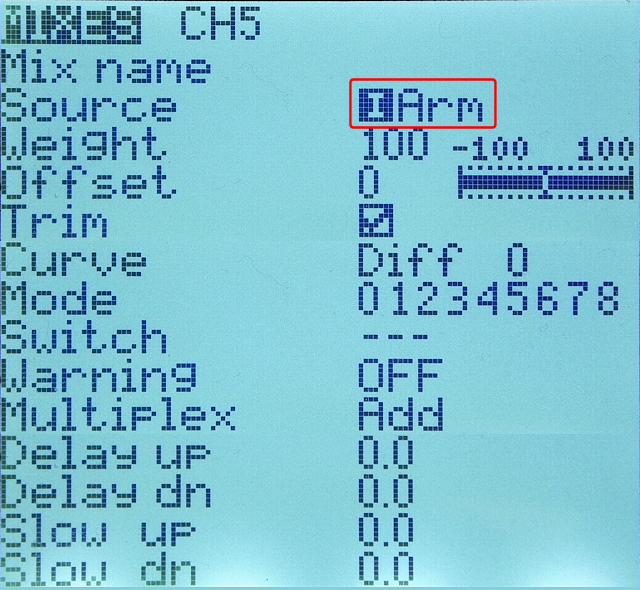
 Allocate virtual channels to physical channels 5-8.
On the screen above, move cursor to CH5 and press [ENTER] key.
Allocate virtual channels to physical channels 5-8.
On the screen above, move cursor to CH5 and press [ENTER] key.
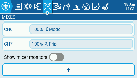
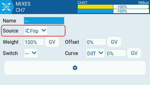
For color display/touch panel models, select "+" at the bottom of the list and press [ENTER] key.
 Then the screen will look like this.
There are many settings that can be made regarding the behavior of virtual channels, but this time we will only assign channel numbers.
Then the screen will look like this.
There are many settings that can be made regarding the behavior of virtual channels, but this time we will only assign channel numbers.
In "Source" field, select virtual channel
When we defined virtual channels, we specified the same number as the physical channel, so simply set
For details on these all setting items, see MODEL MIXES setting items explanation .
 Color display/touch panel models can be set in the same way, just with a different screen design.
Select
Color display/touch panel models can be set in the same way, just with a different screen design.
Select
 When MIXES screen looks like this, setting is complete.
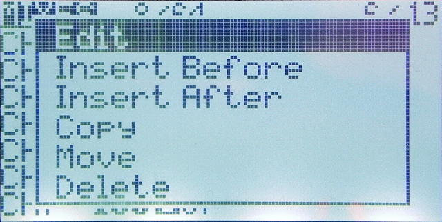 If you place cursor on a channel that has already been entered and press and hold [ENTER] key, a screen like this will be displayed.
You can edit, insert new channel settings before and after, copy, move, and delete.
If you place cursor on a channel that has already been entered and press and hold [ENTER] key, a screen like this will be displayed.
You can edit, insert new channel settings before and after, copy, move, and delete.
You can also click [ENTER] key on a channel that has already been entered to select, and then UP / DOWN cursor keys, etc, to change the display order.
On radio: Other screen settings
This time, no other screen settings will be made. If aircraft to be controlled is a fixed-wing that uses servo motors, logical control signal can be adjusted to match actual servo movable range on OUTPUTS screen . You can also set sub-trim on OUTPUTS screen when the flight path is swept due to problems such as motor balance.Next, let's bind radio and drone and do the first time take off. Please see the following page for details.
Create MODEL, Bind with drone, Test flight