


 MODEL INPUTS setting items explanation
This section describes the setting items on the MODEL INPUTS screen of OpenTX / EdgeTX radio.
このページを日本語で見る
Table of contents
MODEL INPUTS screen functions
This screen lists input devices used for maneuvering. It can also be thought of as a screen that assigns input devices such as sticks, switches, and LOGICAL SWITCHES mounted on the radio to virtual channels defined inside OpenTX/EdgeTX. It is also possible to define multiple weights (reaction intensity) and curves (reaction curve) for one device and set them to switch. You can also split movement of one stick in half from the center and assign it to two different virtual channels.On INPUTS screen, you can define input devices in any order. Input devices are assigned to the actual channel on MIXES screen .
MODEL INPUTS screen explanation
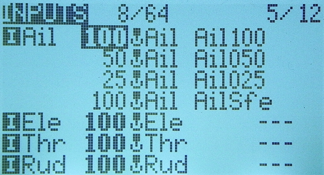 When you open "INPUTS" screen from "MODEL menu", it looks like this.
Here you will see a list of input devices used for maneuvering in current MODEL.
The number of currently registered inputs (number of lines) is displayed to the right of the part labeled "INPUTS" at the top of the screen.
The word "8/64" indicates that 8 lines are currently consumed and up to 64 lines can be defined.
You can set up to 32 "inputs" and up to 64 "lines".
When you open "INPUTS" screen from "MODEL menu", it looks like this.
Here you will see a list of input devices used for maneuvering in current MODEL.
The number of currently registered inputs (number of lines) is displayed to the right of the part labeled "INPUTS" at the top of the screen.
The word "8/64" indicates that 8 lines are currently consumed and up to 64 lines can be defined.
You can set up to 32 "inputs" and up to 64 "lines".
Any item can be entered on detailed setting screen (described later).
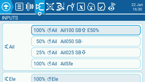 You can set color display / touch panel model in the same way.
| field | item | description |
|---|---|---|
| 1 | Input Name |
The number of the "input (virtual channel)" starting with
The first four "inputs" are automatically assigned four sticks when you create the MODEL. This allocation order can be selected in "RX channel ord (Default channel order)" field on RADIO SETUP screen of "RADIO (SYSTEM) menu". |
| 2 | Weight | This is the 'weight' (rate) to be multiplied by the input value. Input value from Source is multiplied by (Weight value / 100). |
| 3 | Source | The device used for this "input". |
| 4 | Line Name | If you named this "line", it will appear here. When you assign multiple "lines" to one "input", you can give them a name to distinguish each "line". |
| 5 | Switch | This is the switch to enable this "line". If nothing is specified, "---" will be displayed. |
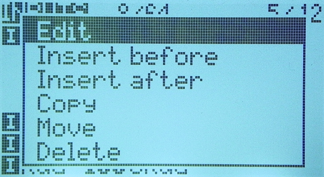 Move cursor to any "Input" on INPUTS screen and press and hold ENTER key to display this menu.
Select "Edit" to open
detailed setting screen
.
Move cursor to any "Input" on INPUTS screen and press and hold ENTER key to display this menu.
Select "Edit" to open
detailed setting screen
.
MODEL INPUTS setting items explanation

| item | description |
|---|---|
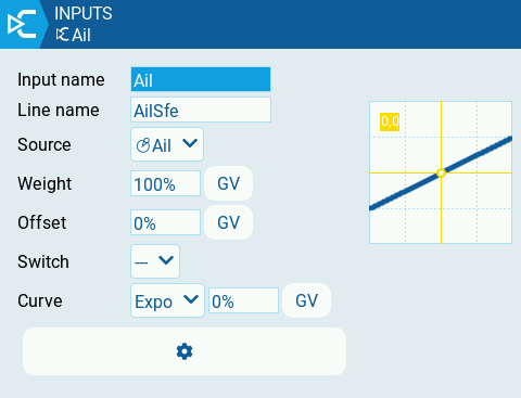
| Input (Input name) | You can give this 'input' a name. Enter up to 3 alphanumers, spaces, and hyphens. |
| Name (Line name) |
You can give this 'line' a name. Enter up to 6 alphanumers, spaces, and hyphens.
When you assign multiple 'line's to one 'input', you can give a name here to distinguish each 'line'.
See Toggle input settings during flight: assign multiple 'lines' to one 'input' for multiple 'line' assignments. |
| Source |
Specifies the device used for input.
In addition to physical devices such as sticks, switches and dials (Pot: Potentiometer), you can also specify MAX (constant always returns 100), Cyclic (defined on the Heli Setup screen),
trim switches
, channel values and more.
It is also possible to specify a different device for each 'line'.
If you move the stick, switch, etc. while editing this item, it will be selected as input device. |
| Weight |
Specifies the 'weight' (rate) to be multiplied by the input value.
Input value from Source is multiplied by (Weight value / 100).
Specify in the range of + 100% to 0%.
You can also select a
global variable
by pressing and holding ENTER while editing.
For example, if you set 50 here, the value when the input device (eg stick) is moved to the maximum will be -50 to +50 instead of -100 to +100. * You can invert the value by specifying a negative Weight value, but do not use a negative value here. Otherwise the trim will work in the opposite direction. If you want to invert the value, specify it on OUTPUTS screen . |
| Offset |
Specifies the offset value to be added to the input value.
Specify in the range of +100 to -100.
You can also select a
global variable
by pressing and holding ENTER while editing.
For example, if you set 10 here, the median value of the input device (for example, when you lift your finger off the stick) will be 10 instead of 0. |
| Curve |
Specifies a reaction curve that determines the output value for the input value from the Source.
Input value is converted according to the curve (function) specified here.
For details, see
MODEL CURVES screen explanation / How to use curves
.
MODEL CURVES screen explanation / How to use curves
|
| Modes |
Specifies the flight mode in which this 'line' is enabled.
If nothing is specified here, it will be enabled in all flight modes.
Flight mode is set on FLIGHT MODES screen of MODEL menu.
How to use flight mode / How to use trim and global variables
|
| Switch |
Specifies the switch to enable this 'line'.
It is always enabled when nothing is specified here.
* Do not specify Switch when you do not want to assign multiple 'line's to this 'input'. |
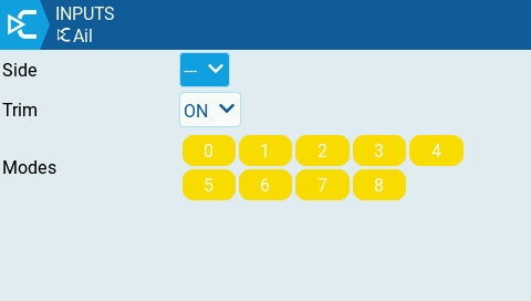
| Side |
Specifies the input range for which this 'line' setting is valid.
If you select "---", it will be valid in the entire range of Source values. If you select "x>0", it will be valid in the upper half of the median value of Source. If you select "x<0", it will be valid in the lower half of the median value of Source. In the invalid range, the reaction will be linear. |
| Trim |
Specify whether to include (ON) or not include (OFF) the adjustment value of
trim switches
in the value of this 'line'.
Alternatively, you can specify which trim switch (Rud, Ele, Thr, Ail) to include the adjustment value.
For this setting to take effect, the Trim field for the relevant input must be enabled on both INPUTS screen and MIXES screen . |
 You can set color display / touch panel model in the same way.
Select "GV" button if you want to use
Global Variables
for Weight, Offset, and Curve arguments.
You can set color display / touch panel model in the same way.
Select "GV" button if you want to use
Global Variables
for Weight, Offset, and Curve arguments.
 If you select
Toggle input settings during flight: assign multiple 'lines' to one 'input'
You can assign multiple 'line's that describe different settings to one 'input'.
You can then use a switch or similar to switch between valid 'line' during flight.
In the example in this figure, for one 'input' "Ail", four 'line's named "Ail100", "Ail050", "Ail025", "AilSfe" are defined, such that the Weight is 100, 50, 25, 100.
Weights are shown in bold for currently enabled 'line'.
Press and hold ENTER key on INPUTS screen to display a menu like this.
You can insert a new 'line' by selecting "Insert before" or "Insert after".
You can assign multiple 'line's to one 'input'.
When all 'line's become invalid for one 'input', the value that was output until just before is retained.
If you want to assign multiple 'line's, add a line with Weight 100% and no Switch specified (fail safe default) at the end. Then, if you accidentally set the Switch to disable all other 'line's, this 'line'(failsafe default) will take effect.