


 Basics of OpenTX/EdgeTX radio operation
Here, we will introduce basics of OpenTX/EdgeTX radio operation.
The same operation is possible with any radio that uses OpenTX / EdgeTX. However, keyswitch assignments / functions differ depending on model, and screen / menu configuration differs depending on installed version of OpenTX / EdgeTX.
このページを日本語で見る
Table of contents
-
RadioMaster Zorro 2.4GHz 16CH Hall Sensor Gimbals

RadioMaster 2022/02 USD89.99
On-board firmware:EdgeTX(OpenTX)
Featuring an ergonomic design, large bright LCD screen in the perfect viewing position, travel adjustable HALL sensor gimbals, a nano size external RF module bay

 (US)
(UK)
How to use RadioMaster Zorro
(US)
(UK)
How to use RadioMaster Zorro
Screen navigation
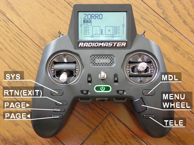 OpenTX/EdgeTX radio screen is basically navigated using keys.
Depending on the model, scroll wheels are used instead of keys, and key assignments are different.
The table below summarizes the features used for OpenTX/EdgeTX navigation.
Check which key each function is assigned to in your radio.
OpenTX/EdgeTX radio screen is basically navigated using keys.
Depending on the model, scroll wheels are used instead of keys, and key assignments are different.
The table below summarizes the features used for OpenTX/EdgeTX navigation.
Check which key each function is assigned to in your radio.
| Name of control | Function | Description |
|---|---|---|
| ENTER | Decide / Confirm | Confirm the change / input. Or select an item. |
| EXIT/RETURN | Cancel / Back | Cancel the change / input. Or return to the previous screen. |
| PAGE | Screen switching | In the setting screen consisting of multiple pages, move to the next page / previous page. LEFT / RIGHT cursor keys or [PAGE] key are used. |
| CURSOR | Move cursor / selected position | Move the cursor. UP / DOWN cursor keys or cross cursor keys, scroll wheel, e.t.c. are used. |
| MODEL/SYSTEM | Calling MODEL / RADIO menu | Call the MODEL / RADIO(SYSTEM) menu. Press and hold LEFT / RIGHT cursor keys, ENTER key or dedicated [MDL][SYS] key, e.t.c. are used. |
How to enter/edit strings
- Enter edit mode
- Move cursor to character string area and press [ENTER] key to enter edit mode.
- Character selection
- In edit mode, you can use up / down cursor keys or scroll wheel to change character at the cursor position. You can select alphanumericals, white spaces, and hyphens.
- Switching uppercase / lowercase
- You can switch the character at the cursor position between uppercase and lowercase by pressing and holding [ENTER] or cursor keys.
- Move cursor
- Press [ENTER] key to confirm the character you are typing, and then use left / right cursor keys or scroll wheel to move to the next character or the previous character.
- Confirmation of input field
- If you press the [ENTER] key again after confirming the entered character, the character string in the input field will be confirmed.
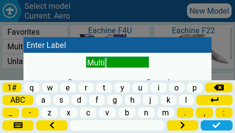 EdgeTX Ver2.8.0 or later touch panel models can use the software keyboard shown in the figure.
Tap the character string area to enter edit mode and software keyboard will be display.
If you select [EXIT] after completing the input, the entered character string will be confirmed.
EdgeTX Ver2.8.0 or later touch panel models can use the software keyboard shown in the figure.
Tap the character string area to enter edit mode and software keyboard will be display.
If you select [EXIT] after completing the input, the entered character string will be confirmed.
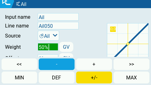 Depending on the type of input area, a keyboard like this will appear.
Tap [-][+] to increase or decrease the value by one step (eg 1).
Tap [<<][>>] to increase or decrease the value by multiple steps (eg 10).
Tap [MIN][MAX] to set the minimum/maximum value that can be entered for that item.
Tap [DEF] to set the default value (often zero) for that item.
Tap [+/-] to reverse the sign of the input value.
Screen configuration
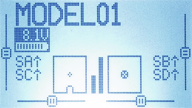
Main screen (monochrome display model)
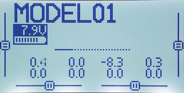 This is "Main screen" of monochrome display model.
OpenTX/EdgeTX can register aircraft information of 60 aircraft from No01 to No60 as "MODEL"s and switch between them for control.
Large "MODEL 01" displayed at the top of the screen is the name of currently selected model.
Below the model name, remaining battery level of radio is displayed.
Numbers listed below are stick position information (-100 to +100).
This is "Main screen" of monochrome display model.
OpenTX/EdgeTX can register aircraft information of 60 aircraft from No01 to No60 as "MODEL"s and switch between them for control.
Large "MODEL 01" displayed at the top of the screen is the name of currently selected model.
Below the model name, remaining battery level of radio is displayed.
Numbers listed below are stick position information (-100 to +100).
On the main screen, there are four types of screens that show the status of sticks and switches with pictures and numerical values, and there is a "CHANNELS (MIXERS) MONITOR" screen, which can be switched with [PAGE] key, etc,. Also, on the screen where horizontal line and horizontal dotted line are displayed in the center as shown in the figure, you can switch display contents with cursor keys, etc,. From main screen, you can also call up " Custom Telemetry Screen " displays telemetry information from the aircraft.
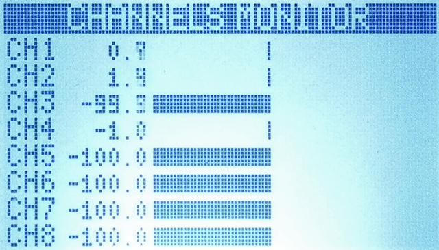 This is "CHANNELS (MIXERS) MONITOR" (Output Monitor) screen.
Value of each channel output from the radio (transmitter) is displayed as a bar graph.
You can see the actual output value of each channel processed and synthesized on
MIXES screen
(described later) of "MODEL menu".
This is "CHANNELS (MIXERS) MONITOR" (Output Monitor) screen.
Value of each channel output from the radio (transmitter) is displayed as a bar graph.
You can see the actual output value of each channel processed and synthesized on
MIXES screen
(described later) of "MODEL menu".
Make sure bar graph moves smoothly as you move each stick.
 This is one of the main screens, Input Monitor screen.
Current input state of sticks and switches recognized by radio is displayed as an illustration.
This is one of the main screens, Input Monitor screen.
Current input state of sticks and switches recognized by radio is displayed as an illustration.
Make sure illustration moves smoothly as you move each stick.
If you feel something is wrong with actual flight or drone simulator , look at Output Monitor screen above and this screen to make sure the radio is working properly. Try stick calibration .
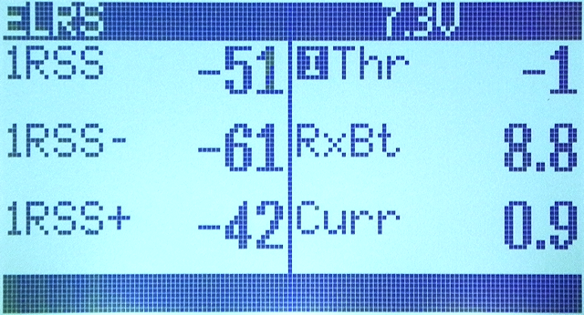 Custom telemetry screen
can also be invoked from main screen that can display
telemetry
, sticks, switches and other information while piloting.
This screen can be called up by pressing [TELE] key or pressing and holding [PAGE] key while the main screen is displayed.
The procedure for calling this screen differs depending on the radio.
Custom telemetry screen
can also be invoked from main screen that can display
telemetry
, sticks, switches and other information while piloting.
This screen can be called up by pressing [TELE] key or pressing and holding [PAGE] key while the main screen is displayed.
The procedure for calling this screen differs depending on the radio.
MODEL DISPLAY screen explanation / How to display telemetry etc. on the radio screen
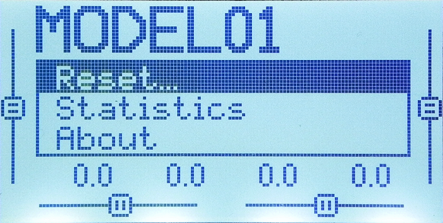 You can bring up this menu by clicking [ENTER] key on main screen.
Press [EXIT] key to return to main screen.
You can bring up this menu by clicking [ENTER] key on main screen.
Press [EXIT] key to return to main screen.
[Reset]: If you select this, a submenu will be displayed, and you can reset timer and telemetry used during maneuvering individually. Select "Flight" in submenu to reset all timers and telemetry at once.
[Statistics]: Usage status of radio so far is displayed.
[About]: You can see the credits of OpenTX/EdgeTX developers.
Main screen (color display / touch panel model)
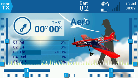 This is main screen of color display model.
At the top of the screen is top bar, which shows radio's battery voltage, speaker volume, RSSI bar graph, date and time.
This is main screen of color display model.
At the top of the screen is top bar, which shows radio's battery voltage, speaker volume, RSSI bar graph, date and time.
In this example, In the center of the screen, value of Timer1 of selected MODEL is displayed in the upper left, "Outputs" screen that displays the output value of the transmitter in the lower left, and the name of selected MODEL ("Aero" in this example screen) and image assigned to this MODEL are displayed.
At the edge of screen, dials (Pot: Potentiometer), throttle, and elevator trim status are displayed at the left and right edges, and dials, 6-position switch, ladder, and aileron trim status are displayed at the bottom edge.
These screen layouts can be changed in " Screens Settings " menu per model. Therefore, different screens may be set depending on the product.
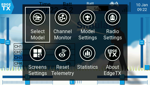 If you tap the top bar (touch panel model) or click [ENTER] key on the main screen, a menu like this (main navigation menu) will appear.
You can scroll the menu by press cursor keys, etc. or dragging screen left or right.
If you tap the top bar (touch panel model) or click [ENTER] key on the main screen, a menu like this (main navigation menu) will appear.
You can scroll the menu by press cursor keys, etc. or dragging screen left or right.
- Select Model
- You can select MODEL to flight. Displays MODELSEL screen. Press and hold [ENTER] on MODELSEL screen to create, copy, move, or delete MODEL.
- Channel Monitor (Output Monitor)
- Value of each channel output by radio (transmitter) is displayed as bar graphs.
- Model Settings
- Open setting screen (MODEL SETUP) of the currently selected MODEL.
- Radio Settings
- Open RADIO (SYSTEM) menu. TOOLS screen will open.
- Screens Settings
- Open layout setting screen of the main screen.
- Reset Telemetry
- Resets telemetry information of the selected MODEL.
- Statistics
- The usage status of the radio so far is displayed.
- About OpenTX/EdgeTX
- The version of OpenTX/EdgeTX installed in radio is displayed.
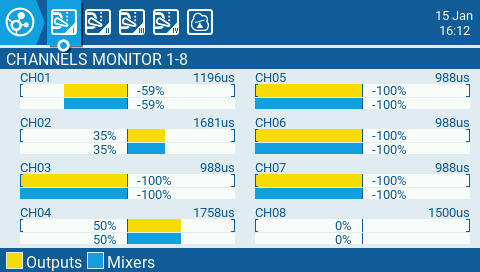 If you select "Channel Monitor" from the main navigation menu, you will see a screen like this.
Information for all 32 channels is displayed on 4 pages.
Value of each channel output from the radio (transmitter)(Upper row: yellow) and
value of each channel output from radio mixer(lower row: blue)
are displayed as a bar graph.
You can see the actual output value of each channel processed and synthesized on
OUTPUT screen
and
MIXES screen
(described later) of "MODEL menu".
If you select "Channel Monitor" from the main navigation menu, you will see a screen like this.
Information for all 32 channels is displayed on 4 pages.
Value of each channel output from the radio (transmitter)(Upper row: yellow) and
value of each channel output from radio mixer(lower row: blue)
are displayed as a bar graph.
You can see the actual output value of each channel processed and synthesized on
OUTPUT screen
and
MIXES screen
(described later) of "MODEL menu".
Make sure bar graph moves smoothly as you move each stick.
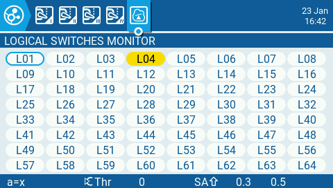 On page 5 of “CHANNELS MONITOR” screen is the “LOGICAL SWITCH MONITOR” screen.
Lists the state of
logical switches
.
On page 5 of “CHANNELS MONITOR” screen is the “LOGICAL SWITCH MONITOR” screen.
Lists the state of
logical switches
.
 If you select "Reset Telemetry" from the main navigation menu, you will see a screen like this.
You can reset
timer
and
telemetry
used during maneuvering individually.
Select "Reset Flight" to reset all timers and telemetry at once.
If you select "Reset Telemetry" from the main navigation menu, you will see a screen like this.
You can reset
timer
and
telemetry
used during maneuvering individually.
Select "Reset Flight" to reset all timers and telemetry at once.
How to change radio screen design / How to use Screens Settings menu
How to set or change Splash Screen / Background Image / Model Image
MODEL menu
Press [MDL] key, etc. on main screen to enter "MODEL menu". In the MODEL menu, there are pages related to "MODEL" of aircraft to be operated, as shown in the table below, which can be switched using [PAGE] key, etc. Press [EXIT] key to return to main screen.To fly a new aircraft, set up a new "MODEL" by entering each of screens below. Of these, the minimum required screens for operating Tiny Whoops are only three screens: SETUP, INPUTS, and MIXES. For how to set the "MODEL", see Create MODEL, Bind with drone, Test flight .
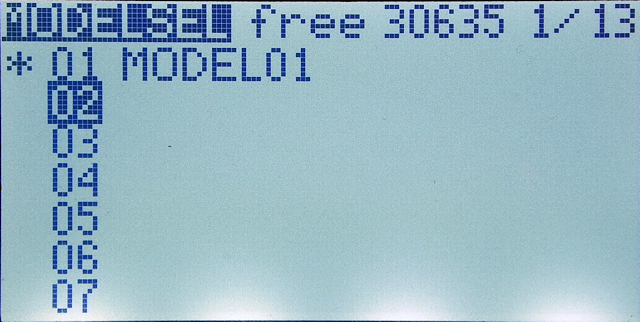 On monochrome display models, pressing [MDL] key opens
MODELSEL screen
first. You can select the model you want to operate and set.
On monochrome display models, pressing [MDL] key opens
MODELSEL screen
first. You can select the model you want to operate and set.
If you press [PAGE] key etc. on this screen, you will switch to each page in the list below.
 On color display models, pressing [MDL] key, etc. will first open
SETUP screen
.
Basic settings for the currently selected model can be performed.
To open
MODELSEL screen
, press and hold a key such as [MDL] key.
On color display models, pressing [MDL] key, etc. will first open
SETUP screen
.
Basic settings for the currently selected model can be performed.
To open
MODELSEL screen
, press and hold a key such as [MDL] key.
If you press [PAGE] key or tap the icon on the top bar at the top of the screen, you will switch to each page in the list below.
| No | menu | function |
|---|---|---|
| 01 | MODELSEL |
Select model you want to control from models (aircraft) stored in the radio.
MODELSEL screen explanation / Create / move / copy / delete model
|
| 02 | SETUP |
This screen is for basic settings of selected model. You can also select communication protocol with aircraft and bind it from this screen.
MODEL SETUP setting items explanation
|
| 03 | HELI SETUP |
Setting screen for radio-controlled helicopters. Not used on drones or other aircraft.
This menu will not be displayed if the build option "noheli" is enabled when updating radio firmware.
On this screen, set CCPM (cyclic collective pitch mixing) for radio-controlled helicopters. This is output to CYC1, CYC2, CYC3 and assigned to the channel on MIXES screen. |
| 04 | FLIGHT MODES | You can prepare multiple trim and global variable settings (flight mode) and switch between them during flight. Trim switching is mainly used for radio controlled gliders. Global variables can be used anywhere on the MODEL settings screen. By switching this, you can change the flight characteristics and so on.
How to use flight mode / How to use trim and global variables
|
| 05 | INPUTS | This screen lists input devices used for maneuvering. It can also be thought of as a screen that assigns input devices such as sticks, switches, and LOGICAL SWITCHES mounted on the radio to virtual channels defined inside OpenTX/EdgeTX. It is also possible to define multiple weights (reaction intensity) and curves (reaction curve) for one device and set them to switch. You can also split movement of one stick in half from the center and assign it to two different virtual channels.
MODEL INPUTS setting items explanation
|
| 06 | MIXES | This screen defines which input device (virtual channel) defined on INPUTS screen is transmitted to which physical channel of receiver (aircraft). The output values of multiple virtual channels can be mixed at a specific ratio (weight) to control one physical channel, or one virtual channel can control multiple physical channels at the same time. Weights, curves, etc. can be set here as well.
MODEL MIXES setting items explanation
|
| 07 | OUTPUTS | This screen is for adjusting maximum value, minimum value of pulse length, trim, etc. for each physical channel defined on MIXES screen. Adjust logical control signal to fit actual servo range of motion. You can also reverse direction of rotation of servo.
MODEL OUTPUTS setting items explanation
|
| 08 | CURVES |
It is a screen to define user's own custom curves (reaction curve). You can define 32 types of custom curves from CV1 to CV32. Defined curves are used on INPUTS screen and MIXES screen.
MODEL CURVES screen explanation / How to use curves
|
| 09 | LOGICAL SWITCHES |
This screen defines a virtual switch that takes two values, TRUE and FALSE. This switch automatically turns ON / OFF according to various specified conditions and can be used as a trigger to call other functions. 64 types of logical switches L01 to L64 can be defined.
MODEL LOGICAL SWITCHES screen explanation / How to use logical switches
|
| 10 | SPECIAL FUNCTIONS |
This is the screen that assigns 20 types of pre-installed actions (functions) in OpenTX/EdgeTX to radio switches and logical switches e.t.c. Settings here are saved for each model.
How to use Special Functions / Global Functions
|
| 11 | CUSTOM SCRIPTS | This is the screen that defines "Mix" type Lua script that describes the processing that replaces MIXS screen. |
| 12 | TELEMETRY |
Make settings related to telemetry data obtained from receiver. You can adjust display of power supply voltage of receiver, and adjust RSSI signal strength to notify signal lost alarm.
MODEL TELEMETRY screen explanation / How to use telemetry
|
| 13 | DISPLAY |
This screen is for setting which information, such as telemetry from the aircraft, is to be displayed on radio's four custom telemetry screens.
MODEL DISPLAY screen explanation / How to display telemetry etc. on the radio screen
|
RADIO(SYSTEM) menu
Press [SYS] key, etc. on main screen to enter "RADIO(SYSTEM) menu". In the RADIO(SYSTEM) menu, there are pages related to to radio settings, as shown in the table below, which can be switched using [PAGE] key, etc. Press [EXIT] key to return to main screen.| No | menu | finction |
|---|---|---|
| 01 | TOOLS | Display a list of "One-Time" type Lua scripts stored in the /SCRIPTS/TOOLS folder of microSD card. Select each script and press [ENTER] to launch the script. |
| 02 | SD-HC CARD SD CARD | You can check contents (list of folders and files) of microSD card inserted in radio like Windows Explorer / Mac Finder. You can update radio's firmware by selecting binary file. |
| 03 | RADIO SETUP |
You can set the radio. For details on each item, see RADIO SETUP setting items explanation.
RADIO SETUP setting items explanation
|
| 04 | THEMES |
You can switch the radio screen design (theme) (color display model only). See
How to change radio screen design / How to use Screens Settings menu
for details.
How to change radio screen design / How to use Screens Settings menu
|
| 05 | GLOBAL FUNCTIONS |
This is the screen that assigns 20 types of pre-installed actions (functions) in OpenTX/EdgeTX to radio switches and logical switches e.t.c. Settings here are common to all models.
How to use Special Functions / Global Functions
|
| 06 | TRAINER | When using radio as a trainer (teacher) mode, set signals (channel assignment and weight) sent from student's radio. In trainer mode, student's radio connects to trainer's radio and trainer's radio connects to aircraft. Trainer can assist student in maneuvering. |
| 07 | HARDWARE | You can refer to hardware related information of radio. You can calibrate sticks and battery. You can also enable/disable and name sticks and switches. |
| 08 | VERSION | Shows the version of OpenTX/EdgeTX installed on radio. |